2026 How to Choose a Condensate Return System?

Choosing a condensate return system in 2026 requires more than comparing pump prices. The right design protects heat, equipment, water quality, and production stability. It must also fit the plant’s actual operating habits.

Steam engineer David Holland offers a useful warning: “A return line must be designed for condensate, flash steam, and changing pressure—not water alone.” That principle matters beside a boiler room. A hot receiver may vent visibly. A small pump may cycle every few seconds. A poorly sized line may hammer when flash steam meets cooler condensate.

A reliable condensate return system begins with measured conditions. Record steam pressure, condensate temperature, return distance, vertical lift, and peak flow. Check whether the plant receives clean condensate or contaminated drains. A food process, hospital, and chemical facility may need very different materials and controls.

Look closely at the receiver, pump, check valves, strainers, insulation, and instrumentation. Automatic pump traps can suit pressurized systems, while electric pumps may provide better control at changing loads. Flash tanks can reduce pressure safely and recover useful heat. Sometimes, a simple gravity return performs better than complex equipment.

Do not trust old drawings completely. They may hide abandoned branches, blocked vents, or undersized returns. That is where experience helps, though experience can also create blind spots. A design that worked for ten years may fail after production expands.

This guide examines practical selection criteria, energy recovery, maintenance access, corrosion risks, and lifecycle cost. The best choice is not always the most sophisticated one. It is the one that returns condensate quietly, safely, and consistently.

2026 How to Choose a Condensate Return System?

What Is a Condensate Return System and Why Is It Important?

What Is a Condensate Return System and Why Is It Important?

A condensate return system collects hot water formed after steam releases its heat. It sends this water back to the boiler feedwater circuit. The system usually includes return piping, traps, pumps, receivers, valves, and monitoring points. Without proper recovery, valuable heat, treated water, and chemicals leave the plant through the drain.

The U.S. Department of Energy’s Steam Tip Sheet 13 reports that increasing condensate return by 10% can reduce boiler fuel use by about 1%, depending on operating conditions. Returned condensate also reduces the energy needed for feedwater heating. This matters in factories with long steam lines, frequent process cycles, or high makeup-water demand. However, condensate is not automatically clean. Flash steam, corrosion products, and leaking heat exchangers can contaminate the return line. A poorly sized pump may also cause water hammer or unstable boiler levels. These details are easy to underestimate.

Tips: Measure temperature, pressure, flow, and conductivity at key return points. The ASHRAE Handbook recommends evaluating pressure loss and drainage conditions when designing steam systems. Inspect traps regularly, but do not replace every trap on a fixed schedule. A simple survey may reveal more than assumptions. Review the design after seasonal load changes, because yesterday’s return rate may not represent today’s operation.

How Does a Condensate Return System Work?

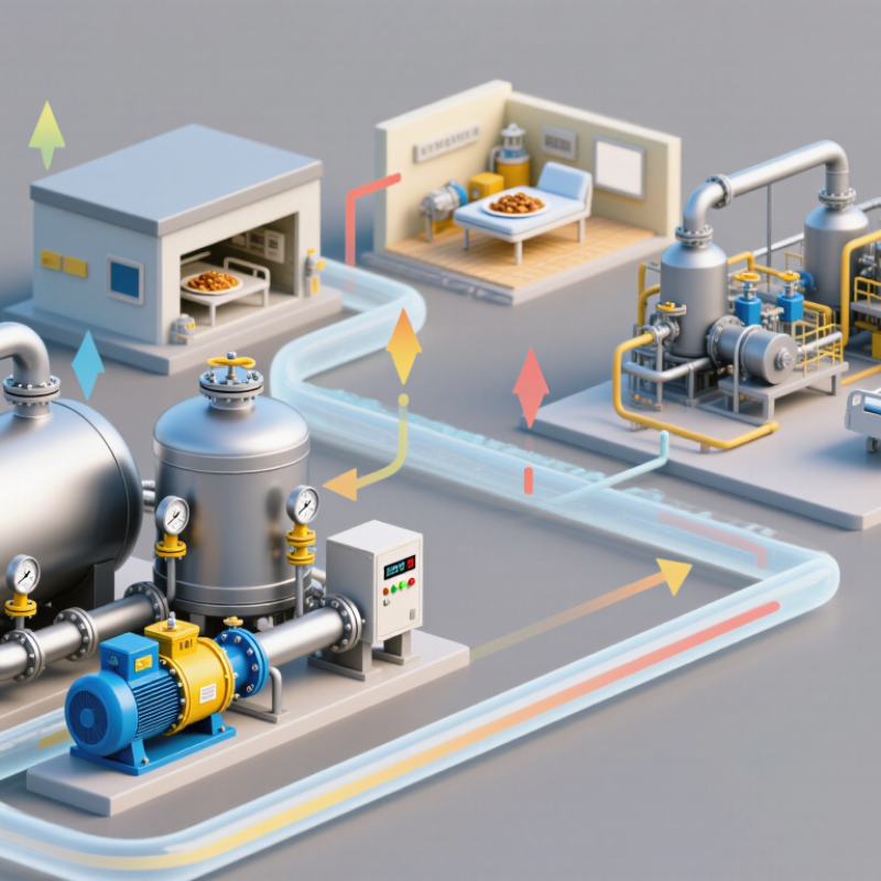
A condensate return system collects hot water formed when steam releases heat. The condensate leaves heat exchangers, coils, and process vessels through steam traps. Each trap allows condensate to pass while limiting live steam loss. The return line then carries this water toward a receiver or directly to the boiler feed system.

Pressure differences often move condensate through short, well-sloped pipes. Longer systems usually need a receiver tank and condensate pump. The receiver stores returning water, while the pump sends it back when the boiler feed pressure is higher. Check valves help prevent reverse flow. Venting is also important because flash steam can form when hot condensate enters a lower-pressure receiver. Without enough space, the tank may surge, and the pump can cycle badly.

A reliable design depends on temperature, pipe length, elevation, pressure, and expected flow. Pipe insulation reduces heat loss and protects workers from hot surfaces. Proper drainage limits water hammer, which can sound like a heavy knock inside the line. In field inspections, unusual noise often reveals poor slope, blocked traps, or unstable pressure. I have found that simple layouts are easier to maintain, but simplicity can hide weak capacity calculations. Engineers should check peak condensate loads rather than average loads alone. Materials must also resist corrosion, especially where treated water, oxygen, or contaminated condensate enters the system. Small errors matter. A system may operate quietly for months before poor drainage becomes expensive.

2026 How to Choose a Condensate Return System? - How Does a Condensate Return System Work?
Selection and Operating Dimension Gravity Return System Open Receiver and Pump System Closed Pressurized Return System Recommended Engineering Check
How the system works Condensate flows from steam-using equipment to a return main by gravity when the available elevation head is greater than pipe and fitting losses. Condensate drains into a receiver, where a level-controlled pump transfers it to the boiler feedwater or condensate treatment system. Condensate remains in a sealed receiver or return header and is moved by residual steam pressure, differential pressure, or a pressurized condensate pump. Confirm the pressure and elevation at every connection, including the equipment outlet, return header, receiver, and feedwater destination.
Typical pressure condition Return line pressure is close to atmospheric pressure; adequate static head is required. Receiver is normally near atmospheric pressure, approximately 0 barg, while the pump creates the required discharge pressure. Return pressure is maintained above atmospheric pressure; the design value commonly depends on the boiler-house and process-water pressure. Use absolute pressure for thermodynamic calculations and gauge pressure for equipment and piping ratings.
Best application Short, continuously descending routes with sufficient vertical drop and low backpressure. Multiple low-level users, long distances, variable loads, or areas where condensate cannot drain directly to the destination. High-temperature condensate recovery, long return routes, limited space, and installations where flash steam and heat loss must be minimized. Select the simplest system that can handle the actual pressure, temperature, elevation, and load variation.
Typical condensate temperature Often about 80–180 °C, depending on the steam pressure and heat loss in the return piping. Usually reduced by flashing and heat release in the receiver; the actual temperature depends on receiver pressure and inlet conditions. Can remain near the saturation temperature of the upstream steam pressure, commonly about 120–190 °C for saturated steam service. Check the maximum operating temperature, design temperature, insulation requirement, and personnel protection requirements.
Typical flow capacity Suitable for stable loads when the pipe can be sized to limit velocity, pressure drop, and water hammer. Suitable for fluctuating loads; pump capacity is commonly selected for peak condensate flow plus an engineering margin. Suitable for continuous or large condensate flows when the return pressure remains within the allowable differential pressure. Size for maximum simultaneous condensate generation, not only the average daily flow.
Flash steam risk High when hot condensate discharges into a lower-pressure return line; two-phase flow can cause noise and water hammer. Expected when hot condensate enters a vented receiver; the receiver must safely vent the generated flash steam. Lower than in an open receiver when pressure is maintained, but flashing can still occur at pressure-reducing devices and downstream of traps. Estimate flash steam whenever condensate pressure falls below its saturation pressure. For example, condensate near 180 °C can produce several percent flash steam when released to near-atmospheric pressure.
Water hammer control Requires continuous pipe slope, adequate drainage, correct trap installation, and avoidance of lift pockets. Requires a properly sized receiver, inlet diffuser or calming arrangement where necessary, and controlled pump cycling. Requires suitable steam traps, check valves, separators, air removal, and gradual pressure transitions. Keep condensate lines self-draining and avoid routing that allows liquid slugs to accelerate into closed valves or elbows.
Steam trap arrangement Use traps that discharge condensate reliably against the available return pressure. Trap differential pressure must be sufficient to discharge into the receiver under all operating conditions. Trap selection must account for the return pressure, minimum differential pressure, start-up load, and possible stall conditions. Verify trap capacity at both minimum and maximum differential pressure; a trap rated only at normal conditions may fail during start-up.
Pipe sizing considerations Size for gravity drainage and limit pressure loss; provide slope toward the collection point. Size the suction line to reduce friction and protect the pump from cavitation; size the discharge line for acceptable velocity. Size for condensate and any two-phase flow, with particular attention to pressure drop and return-line backpressure. Use a recognized piping design method and check liquid velocity, steam velocity, pressure drop, expansion, supports, and drainage points.
Pump and NPSH requirements No pump is normally required if the static head is adequate. Requires sufficient flooded suction head and adequate net positive suction head available to prevent cavitation. May use a pressurized pump, electric pump, pneumatic pump, or pressure-driven pump depending on the system pressure and control philosophy. Compare NPSH available with NPSH required at maximum temperature and minimum receiver level, including line losses.
Energy recovery potential Moderate; heat is recovered, but open or poorly insulated lines can lose sensible heat and generate flash steam. Moderate to high; condensate is recovered, although the vented receiver may release flash steam and heat. High; sealed operation can preserve more sensible heat and reduce flash-steam losses before the condensate reaches the feedwater system. Evaluate recovered water, recovered heat, flash steam utilization, insulation cost, pumping energy, and maintenance cost together.
Materials and corrosion Carbon steel is common for suitable temperature and water chemistry; stainless steel may be required for corrosive or high-purity service. Receiver, pump wetted parts, and piping must tolerate hot water, dissolved gases, treatment chemicals, and repeated thermal cycling. Materials must withstand pressure, temperature, oxygen-related corrosion, and the water chemistry of the closed circuit. Specify material compatibility from the condensate analysis, including pH, conductivity, dissolved oxygen, chlorides, and treatment chemicals.
Controls and instrumentation Basic temperature, pressure, and drain monitoring may be sufficient for simple systems. Normally requires receiver level control, pump start/stop logic, high-level alarm, low-level protection, and check-valve monitoring. Normally requires pressure, temperature, level, differential-pressure, and safety-relief protection with appropriate control logic. Provide alarms for high temperature, high level, low level, pump failure, abnormal return pressure, and loss of condensate flow.
Maintenance profile Relatively low maintenance, but slope, supports, traps, and drains must be inspected regularly. Higher maintenance because pumps, seals, level controls, check valves, and receiver internals require inspection. Requires regular inspection of pressure equipment, traps, valves, controls, safety devices, and insulation. Prepare a maintenance schedule based on operating hours, condensate quality, cycling frequency, and consequences of failure.
Main advantages Simple layout, low equipment count, low electrical demand, and straightforward operation. Flexible routing, good control of variable loads, and practical collection from several low-level sources. Improved heat recovery, reduced flash-steam release, and better suitability for high-temperature condensate return. Compare lifecycle cost rather than purchase cost alone, including energy, water treatment, downtime, and maintenance.
Main limitations Needs favorable elevation and may be vulnerable to backpressure, flashing, and water hammer. Electrical or mechanical equipment adds maintenance, energy use, and potential failure points. Higher design complexity, pressure-system requirements, and stricter control and safety provisions. Reject any arrangement that cannot maintain reliable drainage during start-up, minimum load, maximum load, and equipment shutdown.
Primary selection rule Choose when gravity provides reliable drainage with adequate head and acceptable pressure drop. Choose when condensate sources are below the destination, loads vary significantly, or a common collection point is needed. Choose when preserving condensate temperature and minimizing flash-steam loss justify the added pressure and control requirements. Base the final choice on a hydraulic balance, heat-and-mass balance, safety review, water chemistry review, and lifecycle cost analysis.
Design note: The values shown are typical engineering ranges and selection guidance, not fixed operating limits. Final equipment ratings must be verified against the actual steam pressure, condensate flow, return pressure, elevation profile, water chemistry, local regulations, and applicable pressure-vessel and piping standards.

Which Factors Affect Condensate Return System Selection?

How to Choose a Condensate Return System in 2026

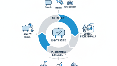
Condensate return system selection begins with the steam network, not the pump catalogue. Measure condensate flow during startup, peak production, and low-load periods. A single average value can hide serious operating problems. Steam pressure, temperature, return distance, elevation, and available space all affect the design. A 10-meter lift may require more pressure than expected when flash steam develops.

Flash steam deserves careful attention. Hot condensate can partially vaporize after pressure drops, creating unstable flow and water hammer. Engineers should check receiver sizing, venting, pipe velocity, and backpressure together. Oversized return lines waste money and may cool condensate unnecessarily. Undersized lines create noise, flooding, and pump overload. Keep it practical.

Material selection depends on condensate chemistry, oxygen exposure, and cleaning conditions. Corrosion can appear slowly inside a pipe and remain unnoticed until leaks interrupt production.

Pumps and controls should handle changing flow without frequent cycling. Level sensors need protection from turbulence and foam. Maintenance access matters, too. A system that performs well on paper may be frustrating to service.

In field reviews, I have found that operators often know the real weaknesses before drawings reveal them. Ask about blocked strainers, cold mornings, failed traps, and unusual knocking sounds. Energy recovery, water quality, safety requirements, and future capacity should also influence the decision. However, not every facility needs the most complex arrangement. A simpler system can be more reliable, although that judgment should be tested against actual measurements.

How to Compare Condensate Return System Types and Components?

2026 How to Choose a Condensate Return System?

Comparing condensate return systems starts with operating conditions, not equipment catalogs. Gravity return works well when condensate can flow downhill naturally. It needs enough elevation and little backpressure. Pumped return suits low-pressure equipment, long pipe runs, or rising discharge lines. Pressurized return can move hot condensate across greater distances, but it demands careful pressure control. I have seen small elevation changes decide whether a gravity system performs reliably. A layout that looks simple on paper may behave differently after startup.

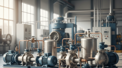
Compare the receiver, pump, steam traps, check valves, vents, controls, and piping as one system. The receiver should handle incoming condensate without excessive turbulence or flashing. Select pumps for temperature, flow, head, and expected cycling. Check valves must prevent reverse flow during shutdowns. Insulated return lines reduce heat loss, yet insulation alone cannot solve poor drainage. Consider water quality too. Oil, rust, and treatment chemicals can damage components or contaminate recovered condensate. This detail is often underestimated.

Tips: Measure peak and average condensate flow separately. Check pressure at the equipment outlet and return destination. Leave access around traps and pumps for inspection. Choose corrosion-resistant materials where chemistry is uncertain. Avoid oversizing every component; oversized pumps may short-cycle and wear faster. No selection is perfect. Review actual operating data after commissioning, because assumptions can be wrong.

2026 How to Choose a Condensate Return System?

How to Compare Condensate Return System Types and Components

Saturated condensate temperature rises with steam pressure. Gravity systems are generally suitable when the return line can drain continuously to a vented receiver. Pumped systems are commonly selected when condensate must be lifted or when backpressure prevents gravity drainage. Pressurized return systems can reduce flashing and preserve useful heat, but they require suitable pressure-rated piping, valves, traps, flash-management equipment, and controls. The temperatures shown are standard saturated-steam reference values and should be verified against the actual operating pressure and design conditions.

How to Select, Install, and Maintain the Right System?

2026 How to Choose a Condensate Return System?

How to Select, Install, and Maintain the Right System?

Selecting a condensate return system starts with measured operating data, not a catalogue image. Record condensate temperature, flow rate, pressure, lift height, and daily load changes. A gravity system may suit short, level pipework. Longer routes usually need a receiver and pump.

Choose materials that tolerate hot water, corrosion, and repeated thermal cycling. Size return lines carefully; undersized pipes can create backpressure and water hammer. Include strainers, check valves, isolation valves, and accessible drains. Steam traps must match the equipment load, not simply the connection size. That mistake is common.

Install the receiver below the equipment outlet whenever possible. Keep return piping sloped toward the receiver, and support it near valves and bends. Insulate hot sections, but leave inspection points visible. During commissioning, check pump starts, receiver level, discharge pressure, and unusual vibration. Small leaks matter.

Maintenance should follow operating evidence. Inspect traps, clean strainers, test level controls, and verify check valves regularly. A temperature log can reveal poor trap performance before production suffers. In field inspections, neglected insulation often causes unnecessary heat loss and condensation around fittings. Digital sensors can help, but they still need calibration. A perfect design on paper may fail when actual loads fluctuate. Review the system after the first month and adjust its controls carefully.