A self priming centrifugal pump is designed to move liquid without repeated manual filling. It can remove air from its suction line and begin pumping again. That ability makes it valuable in wastewater, drainage, agriculture, and process applications.
The operating cycle begins inside the casing. The impeller spins and mixes trapped air with incoming liquid. This mixture enters a separation chamber, where air rises and liquid returns toward the impeller. The pump gradually evacuates air from the suction pipe. Once the pipe fills, normal centrifugal pumping starts. Simple in principle. Not effortless in practice.
As pump engineer Igor J. Karassik put it, “The pump is the heart of any fluid-handling system.” His observation highlights an important point: pump selection affects the entire installation. A self priming centrifugal pump still needs suitable suction piping, adequate liquid level, and correct rotation. A leaking flange can admit air and stop priming. A clogged check valve can create the same problem.
Field technicians often inspect the casing before blaming the motor. They check unusual vibration, a rattling suction line, and declining discharge pressure. These details reveal more than a specification sheet. The pump may appear powerful, yet excessive lift can exceed its practical priming capacity. Fluid temperature and viscosity also change performance.
This guide explains the internal flow path, priming sequence, and common operating limits. It also considers maintenance choices and installation mistakes. One warning remains necessary: “self-priming” does not mean “self-correcting.” The equipment still needs thoughtful design, clean seals, and regular inspection. A small oversight can become a costly interruption.
A self-priming centrifugal pump moves liquid by converting motor power into fluid pressure. Unlike a standard centrifugal pump, it can remove air from the suction line after initial filling. This feature supports faster startup in drainage, irrigation, and process systems.
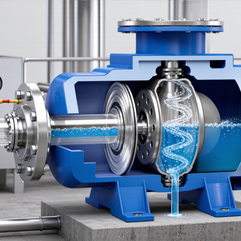
Its main components include the impeller, casing, suction inlet, discharge outlet, check valve, and air separation chamber. The impeller spins inside the casing and creates low pressure near the suction eye. Liquid enters, gains velocity, and leaves through the discharge passage. During priming, the casing holds enough liquid to mix with trapped air. The rotating impeller pushes this mixture into the separation chamber. Air exits through the discharge line, while heavier liquid returns toward the impeller. The cycle continues until the suction pipe fills with liquid. Then, normal pumping begins. The process sounds simple. Field conditions are not.
Tips: Fill the pump casing before its first operation. Check the suction pipe for leaks, loose joints, and sharp bends. A small air leak can stop priming completely. Keep the suction lift within the equipment’s rated limit. Measure it from the liquid surface to the pump centerline. Also inspect the check valve regularly. Debris may hold it open and allow liquid to drain back. From practical maintenance work, many “pump failures” are actually installation problems. Still, performance can vary with liquid temperature, viscosity, and air volume. Confirm operating data against the manufacturer’s technical instructions.
A self-priming centrifugal pump does not create suction from an empty casing. Its casing must hold enough liquid before startup. When the impeller spins, it mixes trapped air with the liquid inside the pump chamber. This lowers the mixture’s density and pushes it toward the discharge side.
The separated air leaves through the discharge pipe. Heavier liquid falls back into the casing and returns to the impeller. This circulation continues while air remains in the suction line. Gradually, the pump removes the air pocket and replaces it with liquid. Suction develops as the pipe becomes filled.
In practice, the process depends on correct installation. A long, narrow suction pipe creates extra resistance. Loose fittings can pull air into the line, even when no liquid leaks outward. The pump may then sound rough, lose flow, or fail to prime. I have seen operators blame the impeller when a small threaded joint caused the real problem.
The casing should be filled before the first start. The pump should also have enough liquid to prevent excessive heat and wear. Self-priming does not mean dry-running is safe. Performance can change with liquid temperature, viscosity, suction lift, and the amount of entrained air. The system may work well in a test area but behave differently after pipework is extended. That difference deserves careful checking.
How Does a Self Priming Centrifugal Pump Work?
Step-by-Step Fluid Flow During the Priming Process
A self-priming centrifugal pump begins with a partly filled casing. The suction pipe may still contain air. When the motor turns the impeller, it mixes trapped air with the available liquid. This air-liquid mixture moves toward the discharge passage. Inside the casing, velocity decreases, allowing air to separate and rise. The heavier liquid returns toward the impeller eye. The cycle repeats. Slowly, the pump removes air from the suction line.
Air leaves through the discharge pipe. Liquid continues recirculating inside the casing. As the suction line becomes liquid-filled, atmospheric pressure pushes more fluid toward the impeller. Priming is complete when a stable liquid column reaches the pump. The impeller can then produce normal centrifugal flow. It sounds simple. It is not. A leaking gasket, oversized suction lift, or blocked vent path can interrupt the cycle. Hydraulic Institute guidance emphasizes correct suction piping, adequate liquid supply, and proper operating conditions. The U.S. Department of Energy reports that pumping systems may consume 25–50% of industrial motor energy, so inefficient priming deserves attention. The International Energy Agency also reports that motor-driven systems use about 53% of global electricity. These figures make small hydraulic losses worth examining. In practice, operators should watch the pressure gauge, listen for air surging, and confirm that discharge flow becomes steady. A short delay may be normal. Repeated dry running is not.
Step-by-step fluid flow during the priming process. The chart shows a representative sequence for a small self-priming centrifugal pump as air is removed from the suction line and liquid flow becomes established.
How it works: At startup, the impeller creates a low-pressure region that draws air and liquid into the pump casing. The air–water mixture is recirculated internally, allowing air to separate and leave through the discharge line. As the suction line fills with liquid, suction vacuum increases and the pump reaches stable water flow.
How Does a Self Priming Centrifugal Pump Work?
How the Impeller and Volute Maintain Continuous Pumping
A self-priming centrifugal pump begins with a casing that retains some liquid after shutdown. This stored liquid is essential for the next start. When the motor turns, the impeller creates a low-pressure area near its eye. Air from the suction pipe enters and mixes with the retained liquid. The impeller throws this mixture outward at high speed.
The volute then slows the flow and converts part of its velocity into pressure. Heavier water moves toward the discharge passage, while lighter air separates and rises inside the casing. Water returns toward the impeller, carrying more air from the suction line. This circulation continues until the suction pipe becomes filled with liquid. Pumping then becomes steady.
The process depends on close clearances and an airtight suction line. A loose flange or damaged seal can let air enter continuously. The pump may sound rough, and discharge pressure can pulse. During field checks, technicians often find that a small leak causes a large delay in priming. The diagram looks simple. Real installations are less forgiving.
The impeller must also avoid excessive wear. A worn eye or blocked passage reduces air-handling ability. The volute shape matters too, because poor flow separation can prolong priming. In some conditions, the pump may appear to run normally while moving very little water. Checking liquid level, suction joints, and internal wear gives a more reliable diagnosis than listening alone.
| System Element | Primary Function | What Happens During Priming | What Happens During Continuous Pumping | Important Operating Consideration |
|---|---|---|---|---|
| Impeller | Transfers mechanical energy from the motor to the liquid and creates centrifugal acceleration. | Rotating liquid carries trapped air toward the casing discharge area while lower pressure forms near the impeller eye. | Continuously increases liquid velocity before the flow enters the volute. | The impeller must remain sufficiently wetted; excessive air, cavitation, or blockage can reduce performance. |
| Volute Casing | Collects flow from the impeller and converts part of its velocity into pressure. | Separates air from liquid as the mixed flow slows and circulates inside the casing. | Maintains a steady pressure rise and directs liquid toward the discharge outlet. | The casing must retain enough liquid after shutdown to support the next automatic priming cycle. |
| Air–Liquid Separation Chamber | Allows entrained air to separate from the liquid before the liquid is recirculated. | Air moves toward the upper region and is gradually expelled through the discharge line. | The chamber limits the amount of air returning to the impeller and supports stable flow. | The actual air-handling capability depends on casing geometry, speed, liquid properties, and suction-pipe design. |
| Suction Pipe | Provides the path through which liquid and air are drawn from the source. | Air is removed from the suction line as the pump creates a lower pressure at the impeller eye. | Delivers liquid with minimal additional air entry or hydraulic loss. | The line should be airtight, continuously rising where practical, and free from high points that can trap air. |
| Discharge Passage | Carries the separated liquid and expelled air away from the pump. | The initial discharge may contain a mixture of air and liquid until the suction line is cleared. | Conveys predominantly liquid at the pump’s operating flow rate and pressure. | Excessive discharge restriction increases system resistance and may lower delivered flow. |
| Retained Priming Liquid | Provides the liquid volume needed to create the liquid–air circulation loop after shutdown. | Mixes with air and is repeatedly recirculated until the suction line becomes liquid-filled. | Becomes part of the normal pumped stream after air has been removed. | If the casing drains completely, manual refilling may be required before the pump can self-prime. |
| Mechanical Seal | Limits leakage along the rotating shaft where it passes through the casing. | Must remain adequately cooled and lubricated by the retained liquid or an approved external arrangement. | Maintains shaft sealing while the impeller rotates under normal hydraulic load. | Extended dry running can overheat and damage many mechanical seal designs. |
| Motor and Shaft | Supplies rotational torque to the impeller at a selected speed. | Maintains impeller rotation while the pump removes air from the suction system. | Balances hydraulic demand with the required power and speed for the duty point. | Operating speed, motor power, and impeller diameter determine much of the pump’s head and flow capability. |
| Priming Sequence | Establishes liquid flow without requiring a separate vacuum priming device in suitable installations. | The pump recirculates retained liquid, separates air, and gradually fills the suction line with liquid. | Once the suction line is full, the pump operates as a conventional centrifugal pump. | Priming time increases with suction-line volume, suction lift, air leakage, and liquid viscosity. |
| Typical Performance Factors | Describe the conditions that influence pumping capacity and reliability. | Air content, suction lift, pipe length, pipe diameter, and retained liquid affect the ability to prime. | Flow rate and pressure depend on the pump curve and the resistance of the connected system. | Actual performance must be verified against the manufacturer’s pump curve and the complete system duty point. |
A self-priming centrifugal pump stores liquid inside its casing after shutdown. During startup, the impeller mixes trapped air with this liquid. The air-liquid mixture moves into a separation chamber. Air exits through the discharge line, while liquid falls back toward the impeller. This cycle gradually fills the suction pipe and creates continuous pumping.
Operating conditions decide whether this process succeeds. The casing usually needs an initial liquid charge. The suction line must remain airtight, with minimal bends and no high points that trap air. Suction lift, fluid temperature, viscosity, and available NPSH also matter.
A practical field check is simple: listen for repeated rattling, watch discharge pressure, and inspect the casing after shutdown. These signs may reveal air leaks or poor priming.
The limits are easy to underestimate. Many self-priming units tolerate air, but they are not designed for unlimited dry running. Excessive solids can wear the impeller and clog internal passages. The U.S. Department of Energy reports that pumping systems may consume 25–50% of an industrial facility’s electricity. Correct sizing therefore affects both reliability and operating cost. Typical applications include construction dewatering, wastewater transfer, agricultural drainage, and process sump service.
Tips: Keep the suction hose short and fully supported. Confirm the manufacturer’s maximum suction lift. A foot valve may help, but it can also collect debris. In real installations, “self-priming” is sometimes treated as maintenance-free. That assumption deserves reconsideration.